25+ voltage controlled oscillator block diagram
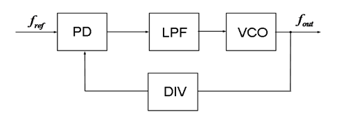
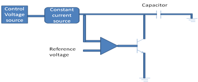
A Phase Locked Loop PLL mainly consists of the following three blocks. The block αvc3 is a current source dependent on voltage vc.
Voltage Controlled Oscillator Usage Of Vco Working And Application
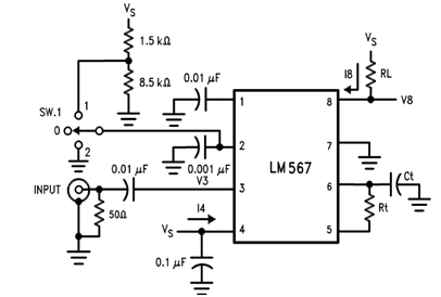
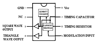
A practical example of a voltage-controlled oscillator VCO is the LM566.

. VCSO Description A block diagram of a typical VCSO is. The arrows indicate the directions of current flows. Download scientific diagram Block diagram of a virtual oscillator controller.
Osc-02 The loop gain of this diagram is LGjω AjωFjω When the loop gain is equal to 1. Voltage Controlled Oscillator KVs Phase Frequency Detector Kp Reference Signal Source Oscillator Outputs. General electronic diagram of voltage-controlled oscillator on the basis.
The block diagram and pin configuration of the Maxim Integrated MAX2623 VCO. Voltage controlled oscillator block diagram and working is explained in this video with basic concept of VCOVoltage Controlled Oscillator in HINDI - https. Linear Feedback Oscillator System Simplified block diagram-Vin Vout Ajw Fjw Vf Fig.
An example of a VCO is the 566 IC unit that provides simultaneously the square-wave and triangular-wave outputs as a function of input. As we have discussed earlier a VCO generates output whose frequency is controlled by the dc input voltage. This case the oscillator could startup at either frequency or jump from one to the other since both meet the oscillation criteria.
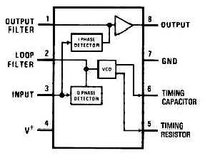
This chapter discusses about the block diagram of PLL and IC 565 in detail. The basic block diagram of PLL is shown in Fig. Voltage controlled oscillator block diagram and working is explained in this video with basic concept of VCOVoltage Controlled Oscillator in ENGLISH - htt.
Lets have a look at the block diagram shown below-Here VCO provides. Basic PLL Block Diagram Therefore the. Between the simulation and the experimental results at the maximum value of the nominal resistance equal to 25 kΩ is less.
Voltage Controlled Oscillator Block Diagram. It is a conventional LC based VCO using dual varactor diodes for voltage. General electronic diagram of voltage-controlled oscillator on the basis of an impedance converter.
Fosc θosc fREF θREF Figure 1. Phase Detection is used to determine the change between the phase angle with the input voltage with which it flows through the loop. Block Diagram of PLL.
The LM566 is a general-purpose VCO that may be used to generate square wave and triangular waveforms as. The block diagram of the SAR.
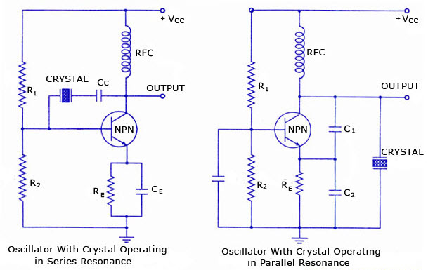
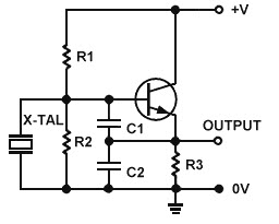
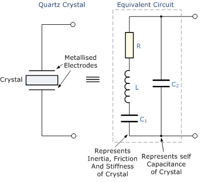
Overview Of Crystal Oscillator Circuit Working With Applications
Variable Frequency Oscillator Circuit With Schematic

Ne566 Function Generator Voltage Controlled Oscillator Vco Circuit Electronic Circuit Projects Function Generator Circuit Projects
Voltage Controlled Oscillator Usage Of Vco Working And Application
Voltage Controlled Oscillator Usage Of Vco Working And Application
Overview Of Crystal Oscillator Circuit Working With Applications
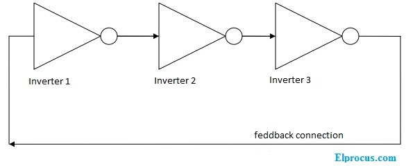
Ring Oscillator Layout Circuit Diagram And Its Applications

Voltage Controlled Oscillator Vco With A 555 Timer Chip Voltage Controlled Oscillator Timer Electronics Circuit
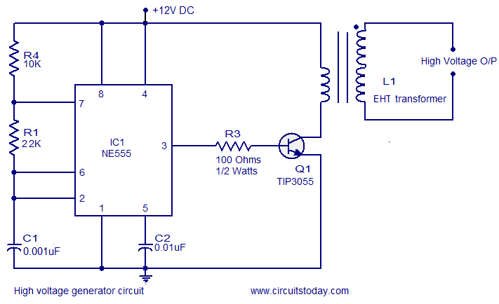
High Voltage Generator Circuit
Voltage Controlled Oscillator Usage Of Vco Working And Application

Voltage Controlled Oscillator Usage Of Vco Working And Application

Voltage Controlled Oscillator Vco Circuit Voltage Controlled Oscillator Electronic Circuit Projects Circuit

Ne566 Function Generator Voltage Controlled Oscillator Vco Circuit Voltage Controlled Oscillator Function Generator Linear Function
Overview Of Crystal Oscillator Circuit Working With Applications

Uc3845 Current Mode Pwm Controller Pinout Feature Datasheet
Voltage Controlled Oscillator Usage Of Vco Working And Application
Voltage Controlled Oscillator Vco